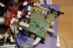
After changing the serial method to transceive ASCII clear text instructions instead if binary data, I found out that that the motors do not react the same when using identical instructions. To ensure that this is not due to a hardware error – and since it does not look like a software error too – I built a small analysis connector which disconnects all connections at all to test every electrical module seperately. This is how the test looked like:

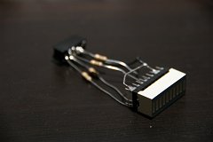
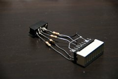
As you can see the green LED shows the state of the corresponding Atmel port bit. For easier testings I simple connected some series resistors of 1.5 k Ohm in line with some LEDs connected to the common ground – with 7-segmend-LEDs, to be more precise. These were than directly soldered on the board connecter:
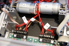
This stuff worked as expected. After this the input ports from the motor control boards were set to high (one after another) to check of these boards work as expected. The most important thing when testing things like this: a wel organised and tidy working environment! ![]()

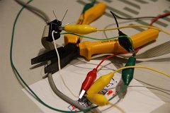
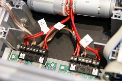
To be honest the reason for this wild flying wires here are was that I had to test this directly at and close to the robot. Since I wanted to have a realistic test case with the original power supply etc. This is why I unmounted the PCBs only this far that I was able to connect all relevant connectors and not resulting in a short circuit.
Using this opportunity I finally labeld the last connectors and cables with this DYMO stuff – since at least anything was disassembled at this moment:

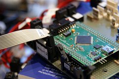
Result so far: No error found. After reassambling everything, all motors worked like they should – allthough nothing was changed. Strange…. ![]()